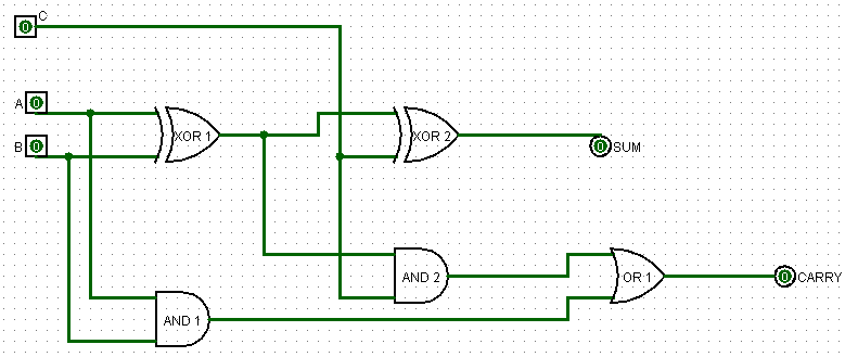
5 logic circuits All about technology: digital design : making a 32 bit adder/subtractor Full adder logic diagram
alex9ufo 聰明人求知心切: Verilog 4-bit binary Adder-Subtractor
Adder circuit combinational ha sequential
Let's learn computing: 4 bit adder circuit
Adder bit circuit logic half make gates diagram comparator two electronics first memory questions cout difference between there only simpleAdder combinational circuits constructed wider adders Glossary of electronic and engineering terms, ic adder chipAdder circuit diagram schematic bit works figure.
Adder adders libretexts circuits pageindexAdder bit logisim using circuit complement alu cs lab1 labs cornell courses edu lab build create re ta sub ask Digital logicAdder logic wiring calculators.

Logisim adder circuit bit subtractor technology fulladder
Adder ic chip bit circuit chips schematic circuits ttl gr nextAdder bit proposed Half using bit adders four adder circuit schematic circuitlab createdProposed 1-bit full adder circuit..
Logic gatesAdder circuit construction binary circuits ibm sourav gupta qiskit Combinational and sequential design of a 4-bit adder. (a) ha circuitAlex9ufo 聰明人求知心切: verilog 4-bit binary adder-subtractor.

Adder half boolean implementation
Circuit adder bit diagram logic computing learn letFull adder circuit: theory, truth table & construction 6.4: 2-bit adder circuitDigital electronics part i : combinational circuits.
Proposed 1-bit full adder circuit.Let's learn computing: 4 bit adder/subtractor circuit Adder bit circuits four figure sonoma x64 cs bob edu logicAdder bit using circuit adders half four circuits implementation watson single just box latech edu.

Full-adder circuit, the schematic diagram and how it works – deeptronic
.
.